
arduino -- IRmottagare med flera möjliga problem
Bakgrund
Hej! Nu till sommaren har jag bestämt mig för att lära mig om och kunna koda kring IRmottagning och sändning. Jag använder mig av ett program som heter arduino (och jag tror att den använder sig av c++ eller c, eller båda). Som start på mitt kodningsäventyr bestämde jag mig att följa en guide (https://learn.sparkfun.com/tutorials/ir-communication/all) som visar hur man kan ta emot och läsa IR-signaler från en TV-kontroll.
Möjliga fel
Dock har jag inte lyckats ta emot en signal från min TV-kontroll. Själv försöker jag aktivt felsöka det kommande problemen jag ska visa er som läser, men min erfarenhet med programmering är väldigt liten så jag kommer knappt någon vart tyvärr. Här ligger vad jag tror kan vara det möjliga felen, i ordning av jobbighet att reda ut;) :
1. elektroniken är sönder.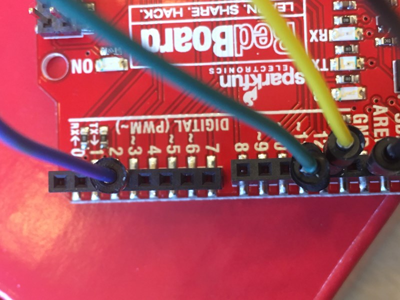 här har en plastdel hamnat på snedden, men jag har ingen aning om det ska vara så eller om den fotfarende är funktionell, trotts lutningen.
2. jag har inte kopplat min "breadboard" på ett korrekt sätt.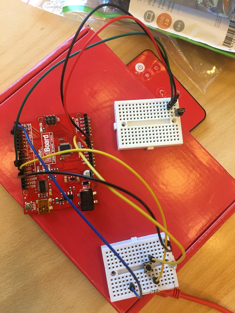
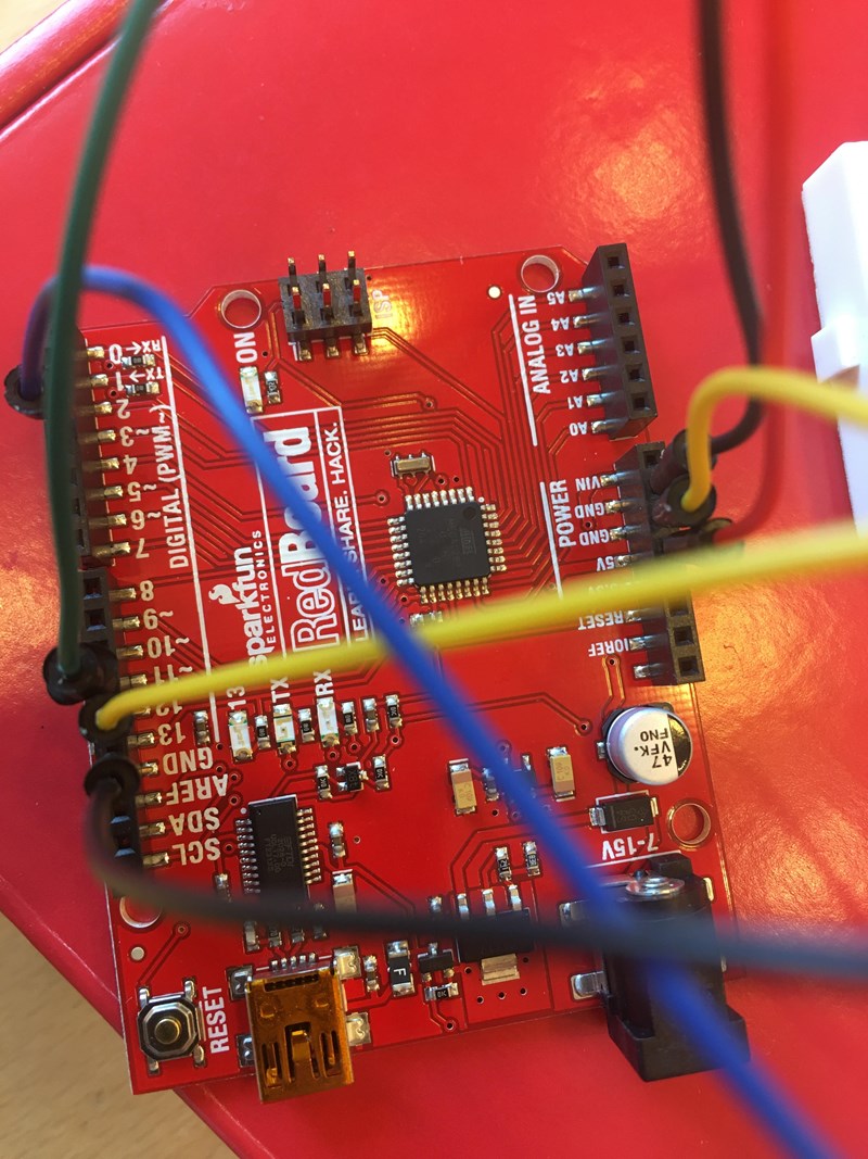 Förhoppningsvis är inte bilderna för röriga, men hursomhelst misstänker jag att jag kan ha kopplat upp något på fel sätt. Såhär ska det se ut enligt hemsidan -->
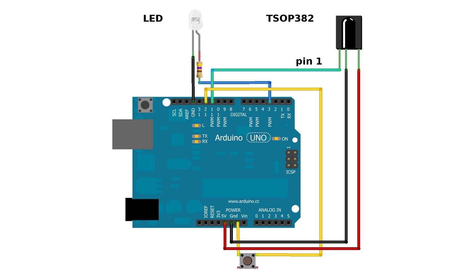
3. Jag har missuppfattat instruktionerna från hemsidans guide (och därav är koden fel).
Här är instruktionerna jag läste (bilden är suddig men länken jag gav förut leder en rakt till den mindre suddiga versionen)
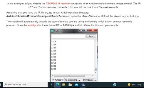
Det fanns dock ingen "IRrecvDemo", utan istället en "ReceiveDemo". Koden för denna var
#include <Arduino.h>

/*
 * Specify which protocol(s) should be used for decoding.
 * If no protocol is defined, all protocols are active.
 * This must be done before the #include <IRremote.h>
 */
//#define DECODE_LG
//#define DECODE_NEC
// etc. see IRremote.h
//
//#define DISABLE_LED_FEEDBACK_FOR_RECEIVE // saves 108 bytes program space
#if FLASHEND <= 0x1FFF  // For 8k flash or less, like ATtiny85. Exclude exotic protocols.
#define EXCLUDE_EXOTIC_PROTOCOLS
#  if !defined(DIGISTUMPCORE) // ATTinyCore is bigger than Digispark core
#define EXCLUDE_UNIVERSAL_PROTOCOLS // Saves up to 1000 bytes program space.
#  endif
#endif
//#define EXCLUDE_UNIVERSAL_PROTOCOLS // Saves up to 1000 bytes program space.
//#define EXCLUDE_EXOTIC_PROTOCOLS // saves around 650 bytes program space if all other protocols are active
//#define IR_MEASURE_TIMING

// MARK_EXCESS_MICROS is subtracted from all marks and added to all spaces before decoding,
// to compensate for the signal forming of different IR receiver modules.
#define MARK_EXCESS_MICROS    20 // 20 is recommended for the cheap VS1838 modules

#define RECORD_GAP_MICROS 12000 // Activate it for some LG air conditioner protocols

/*
 * First define macros for input and output pin etc.
 */
#include "PinDefinitionsAndMore.h"

#include <IRremote.h>

#if defined(APPLICATION_PIN)
#define DEBUG_BUTTON_PIN    APPLICATION_PIN // if low, print timing for each received data set
#else
#define DEBUG_BUTTON_PIN   6
#endif

// On the Zero and others we switch explicitly to SerialUSB
#if defined(ARDUINO_ARCH_SAMD)
#define Serial SerialUSB
#endif

void setup() {
#if defined(IR_MEASURE_TIMING) && defined(IR_TIMING_TEST_PIN)
    pinMode(IR_TIMING_TEST_PIN, OUTPUT);
#endif
#if FLASHEND >= 0x3FFF  // For 16k flash or more, like ATtiny1604. Code does not fit in program space of ATtiny85 etc.
    pinMode(DEBUG_BUTTON_PIN, INPUT_PULLUP);
#endif

    Serial.begin(115200);
#if defined(__AVR_ATmega32U4__) || defined(SERIAL_PORT_USBVIRTUAL) || defined(SERIAL_USB) || defined(ARDUINO_attiny3217)
    delay(4000); // To be able to connect Serial monitor after reset or power up and before first print out. Do not wait for an attached Serial Monitor!
#endif
// Just to know which program is running on my Arduino
    Serial.println(F("START " __FILE__ " from " __DATE__ "\r\nUsing library version " VERSION_IRREMOTE));

// In case the interrupt driver crashes on setup, give a clue
// to the user what's going on.
    Serial.println(F("Enabling IRin..."));

    /*
     * Start the receiver, enable feedback LED and (if not 3. parameter specified) take LED feedback pin from the internal boards definition
     */
    IrReceiver.begin(IR_RECEIVE_PIN, ENABLE_LED_FEEDBACK);

    Serial.print(F("Ready to receive IR signals at pin "));
#if defined(ARDUINO_ARCH_STM32) || defined(ESP8266)
    Serial.println(IR_RECEIVE_PIN_STRING);
#else
    Serial.println(IR_RECEIVE_PIN);
#endif

#if FLASHEND >= 0x3FFF  // For 16k flash or more, like ATtiny1604. Code does not fit in program space of ATtiny85 etc.
    Serial.print(F("Debug button pin is "));
    Serial.println(DEBUG_BUTTON_PIN);

    // infos for receive
    Serial.print(RECORD_GAP_MICROS);
    Serial.println(F(" us is the (minimum) gap, after which the start of a new IR packet is assumed"));
    Serial.print(MARK_EXCESS_MICROS);
    Serial.println(F(" us are subtracted from all marks and added to all spaces for decoding"));
#endif

}

void loop() {
    /*
     * Check if received data is available and if yes, try to decode it.
     * Decoded result is in the IrReceiver.decodedIRData structure.
     *
     * E.g. command is in IrReceiver.decodedIRData.command
     * address is in command is in IrReceiver.decodedIRData.address
     * and up to 32 bit raw data in IrReceiver.decodedIRData.decodedRawData
     */
    if (IrReceiver.decode()) {
        Serial.println();
#if FLASHEND >= 0x3FFF  // For 16k flash or more, like ATtiny1604
        if (IrReceiver.decodedIRData.flags & IRDATA_FLAGS_WAS_OVERFLOW) {
            IrReceiver.decodedIRData.flags = false; // yes we have recognized the flag :-)
            Serial.println(F("Overflow detected"));
#  if !defined(ESP32) && !defined(ESP8266) && !defined(NRF5)
            /*
             * do double beep
             */
            IrReceiver.stop();
            tone(TONE_PIN, 1100, 10);
            delay(50);
#  endif

        } else {
            // Print a short summary of received data
            IrReceiver.printIRResultShort(&Serial);

            if (IrReceiver.decodedIRData.protocol == UNKNOWN || digitalRead(DEBUG_BUTTON_PIN) == LOW) {
                // We have an unknown protocol, print more info
                IrReceiver.printIRResultRawFormatted(&Serial, true);
            }
        }

#  if !defined(ESP32) && !defined(ESP8266) && !defined(NRF5)
        if (IrReceiver.decodedIRData.protocol != UNKNOWN) {
            /*
             * Play tone, wait and restore IR timer, if a valid protocol was received
             * Otherwise do not disturb the detection of the gap between transmissions. This will give
             * the next printIRResult* call a chance to report about changing the RECORD_GAP_MICROS value.
             */
            IrReceiver.stop();
            tone(TONE_PIN, 2200, 10);
            delay(8);
            IrReceiver.start(8000); // to compensate for 8 ms stop of receiver. This enables a correct gap measurement.
        }
#  endif
#else
        // Print a minimal summary of received data
        IrReceiver.printIRResultMinimal(&Serial);
#endif // FLASHEND

        /*
         * !!!Important!!! Enable receiving of the next value,
         * since receiving has stopped after the end of the current received data packet.
         */
        IrReceiver.resume();

        /*
         * Finally check the received data and perform actions according to the received address and commands
         */
        if (IrReceiver.decodedIRData.address == 0) {
            if (IrReceiver.decodedIRData.command == 0x10) {
                // do something
            } else if (IrReceiver.decodedIRData.command == 0x11) {
                // do something else
            }
        }
    }
}
Där "PinDefinitionsAndMore.h" är
/*
 *  PinDefinitionsAndMore.h
 *
 *  Contains pin definitions for IRremote examples for various platforms
 *  as well as definitions for feedback LED and tone() and includes
 *
 *  Copyright (C) 2021  Armin Joachimsmeyer
 *  armin.joachimsmeyer@gmail.com
 *
 *  This file is part of IRMP https://github.com/Arduino-IRremote/Arduino-IRremote.
 *
 *  Arduino-IRremote is free software: you can redistribute it and/or modify
 *  it under the terms of the GNU General Public License as published by
 *  the Free Software Foundation, either version 3 of the License, or
 *  (at your option) any later version.
 *
 *  This program is distributed in the hope that it will be useful,
 *  but WITHOUT ANY WARRANTY; without even the implied warranty of
 *  MERCHANTABILITY or FITNESS FOR A PARTICULAR PURPOSE.  See the
 *  GNU General Public License for more details.
 *
 *  You should have received a copy of the GNU General Public License
 *  along with this program.  If not, see <http://www.gnu.org/licenses/gpl.html>.
 *
 */

/*
 * Pin mapping table for different platforms
 *
 * Platform     IR input    IR output   Tone
 * -----------------------------------------
 * DEFAULT/AVR  2           3           4
 * ATtinyX5     0           4           3
 * ATtiny167    9           8           5 // Digispark pro number schema
 * ATtiny167    3           2           7
 * ATtiny3217   10          11          3 // TinyCore schema
 * ATtiny1604   2           PA5/3       %
 * SAMD21       3           4           5
 * ESP8266      14 // D5    12 // D6    %
 * ESP32        15          4           %
 * BluePill     PA6         PA7         PA3
 * APOLLO3      11          12          5
 */
//#define IRMP_MEASURE_TIMING // For debugging purposes.
//
#if defined(ESP8266)
#define FEEDBACK_LED_IS_ACTIVE_LOW // The LED on my board is active LOW
#define IR_RECEIVE_PIN          14 // D5
#define IR_RECEIVE_PIN_STRING   "D5"
#define IR_SEND_PIN             12 // D6 - D4/pin 2 is internal LED
#define IR_SEND_PIN_STRING      "D6"
#define tone(a,b,c) void()      // tone() inhibits receive timer
#define noTone(a) void()
#define TONE_PIN                42 // Dummy for examples using it
#define IR_TIMING_TEST_PIN      13 // D7
#define APPLICATION_PIN         0 // D3

#elif defined(ESP32)
#define IR_RECEIVE_PIN          15  // D15
#define IR_SEND_PIN              4  // D4
#define tone(a,b,c) void()      // no tone() available on ESP32
#define noTone(a) void()
#define TONE_PIN                42 // Dummy for examples using it
#define APPLICATION_PIN         16 // RX2 pin

#elif defined(ARDUINO_ARCH_STM32) || defined(ARDUINO_ARCH_STM32F1)
// BluePill in 2 flavors
// Timer 3 of IRMP blocks PA6, PA7, PB0, PB1 for use by Servo or tone()
#define IR_RECEIVE_PIN          PA6
#define IR_RECEIVE_PIN_STRING   "PA6"
#define IR_SEND_PIN             PA7
#define IR_SEND_PIN_STRING      "PA7"
#define TONE_PIN                PA3
#define IR_TIMING_TEST_PIN      PA5
#define APPLICATION_PIN         PA2

#elif defined(__AVR_ATtiny25__) || defined(__AVR_ATtiny45__) || defined(__AVR_ATtiny85__)
#include "ATtinySerialOut.h" // Available as Arduino library. saves 370 bytes program space and 38 bytes RAM for digistump core
#define IR_RECEIVE_PIN  0
#define IR_SEND_PIN     4 // Pin 2 is serial output with ATtinySerialOut. Pin 1 is internal LED and Pin3 is USB+ with pullup on Digispark board.
#define TONE_PIN        3
#define IR_TIMING_TEST_PIN 3

#elif defined(__AVR_ATtiny87__) || defined(__AVR_ATtiny167__)
#include "ATtinySerialOut.h"
// For ATtiny167 Pins PB6 and PA3 are usable as interrupt source.
#  if defined(ARDUINO_AVR_DIGISPARKPRO)
#define IR_RECEIVE_PIN   9 // PA3 - on Digispark board labeled as pin 9
//#define IR_RECEIVE_PIN  14 // PB6 / INT0 is connected to USB+ on DigisparkPro boards
#define IR_SEND_PIN      8 // PA2 - on Digispark board labeled as pin 8
#define TONE_PIN         5 // PA7
#define IR_TIMING_TEST_PIN 10 // PA4
#  else
#define IR_RECEIVE_PIN  3
#define IR_SEND_PIN     2
#define TONE_PIN        7
#  endif

#elif defined(__AVR_ATtiny88__) // MH-ET Tiny88 board
#include "ATtinySerialOut.h" // Available as Arduino library. Saves 128 bytes program space
// Pin 6 is TX pin 7 is RX
#define IR_RECEIVE_PIN   3 // INT1
#define IR_SEND_PIN      4
#define TONE_PIN         9
#define IR_TIMING_TEST_PIN 8

#elif defined(__AVR_ATtiny3217__)
#define IR_RECEIVE_PIN  10
#define IR_SEND_PIN     11
#define TONE_PIN         3
#define APPLICATION_PIN  5

#elif defined(__AVR_ATtiny1604__)
#define IR_RECEIVE_PIN   2 // To be compatible with interrupt example, pin 2 is chosen here.
#define IR_SEND_PIN      3
#define APPLICATION_PIN  5
#define TONE_PIN        42 // Dummy for examples using it
#define tone(a,b,c) void() // tone() uses the same vector as receive timer
#define noTone(a) void()

#  elif defined(__AVR_ATmega1284__) || defined(__AVR_ATmega1284P__) \
|| defined(__AVR_ATmega644__) || defined(__AVR_ATmega644P__) \
|| defined(__AVR_ATmega324P__) || defined(__AVR_ATmega324A__) \
|| defined(__AVR_ATmega324PA__) || defined(__AVR_ATmega164A__) \
|| defined(__AVR_ATmega164P__) || defined(__AVR_ATmega32__) \
|| defined(__AVR_ATmega16__) || defined(__AVR_ATmega8535__) \
|| defined(__AVR_ATmega64__) || defined(__AVR_ATmega128__) \
|| defined(__AVR_ATmega1281__) || defined(__AVR_ATmega2561__) \
|| defined(__AVR_ATmega8515__) || defined(__AVR_ATmega162__)
#define IR_RECEIVE_PIN      2
#define IR_SEND_PIN        13
#define TONE_PIN            4
#define APPLICATION_PIN     5
#define ALTERNATIVE_IR_FEEDBACK_LED_PIN 6 // E.g. used for examples which use LED_BUILDIN for example output.
#define IR_TIMING_TEST_PIN  7

#elif defined(ARDUINO_ARCH_APOLLO3)
#define IR_RECEIVE_PIN  11
#define IR_SEND_PIN     12
#define TONE_PIN         5

#elif defined(ARDUINO_ARCH_MBED) // Arduino Nano 33 BLE
#define IR_RECEIVE_PIN      2
#define IR_SEND_PIN         3
#define TONE_PIN            4
#define APPLICATION_PIN     5
#define ALTERNATIVE_IR_FEEDBACK_LED_PIN 6 // E.g. used for examples which use LED_BUILDIN for example output.
#define IR_TIMING_TEST_PIN  7

#elif defined(TEENSYDUINO)
#define IR_RECEIVE_PIN      2
#define IR_SEND_PIN         3
#define TONE_PIN            4
#define APPLICATION_PIN     5
#define ALTERNATIVE_IR_FEEDBACK_LED_PIN 6 // E.g. used for examples which use LED_BUILDIN for example output.
#define IR_TIMING_TEST_PIN  7

#elif defined(__AVR__)
#define IR_RECEIVE_PIN      2 // To be compatible with interrupt example, pin 2 is chosen here.
#define IR_SEND_PIN         3
#define TONE_PIN            4
#define APPLICATION_PIN     5
#define ALTERNATIVE_IR_FEEDBACK_LED_PIN 6 // E.g. used for examples which use LED_BUILDIN for example output.
#define IR_TIMING_TEST_PIN  7

#elif defined(ARDUINO_ARCH_SAMD) || defined(ARDUINO_ARCH_SAM)
#define IR_RECEIVE_PIN      2
#define IR_SEND_PIN         3
#define TONE_PIN            4
#define APPLICATION_PIN     5
#define ALTERNATIVE_IR_FEEDBACK_LED_PIN 6 // E.g. used for examples which use LED_BUILDIN for example output.
#define IR_TIMING_TEST_PIN  7

// On the Zero and others we switch explicitly to SerialUSB
#define Serial SerialUSB

// Definitions for the Chinese SAMD21 M0-Mini clone, which has no led connected to D13/PA17.
// Attention!!! D2 and D4 are switched on these boards!!!
// If you connect the LED, it is on pin 24/PB11. In this case activate the next two lines.
//#undef LED_BUILTIN
//#define LED_BUILTIN 24 // PB11
// As an alternative you can choose pin 25, it is the RX-LED pin (PB03), but active low.In this case activate the next 3 lines.
//#undef LED_BUILTIN
//#define LED_BUILTIN 25 // PB03
//#define FEEDBACK_LED_IS_ACTIVE_LOW // The RX LED on the M0-Mini is active LOW

#else
#warning Board / CPU is not detected using pre-processor symbols -> using default values, which may not fit. Please extend PinDefinitionsAndMore.h.
// Default valued for unidentified boards
#define IR_RECEIVE_PIN      2
#define IR_SEND_PIN         3
#define TONE_PIN            4
#define APPLICATION_PIN     5
#define ALTERNATIVE_IR_FEEDBACK_LED_PIN 6 // E.g. used for examples which use LED_BUILDIN for example output.
#define IR_TIMING_TEST_PIN  7
#endif // defined(ESP8266)

#if !defined (FLASHEND)
#define FLASHEND 0xFFFF // Dummy value for platforms where FLASHEND is not defined
#endif
/*
 * Helper macro for getting a macro definition as string
 */
#define STR_HELPER(x) #x
#define STR(x) STR_HELPER(x)
Om någon misstänker något annat fel och vill veta mer är det bara att fråga på! Till den som läste igenom detta vill jag bara säga tack så hemskt mycket för hjälpen och tålamodet!!

Jag skulle nog försöka ta reda på hur mycket som fungerar, genom att förenkla programmet (eller hämta ett enklare som redan finns), t.ex. ett som bara blinkar eller bara ger ifrån sig en ton.
Det kan vara glapp nånstans. T.ex. är de där kopplingsdäcken (breadboard) inte alltid helt bra när trådarna är tunna, har i alla fall jag råkat ut för.
Man kanske kan koppla in enbart IR-sensorn och en voltmeter (utan något program, bara jord och plus, med rätt spänning) och se om det ger utslag, men det är inte säkert, ifall det kommer bara mycket korta pulser.
Jag ser inte vad som är snett i första bilden.
Edit: Kopplingarna verkar vara rätt, men jag måste förstås fråga: du har väl kopplat den till en spänningskälla när du kör?
